Scope.
Pulling eyes are regularly attached or formed at the end of a wire rope to facilitate installation. The pulling eye on the new rope is connected to a pulling rope or the old rope during the installation process or when re-reeving an existing rope on a machine. They are not intended to be subjected to a load when the machine performs a service operation. This bulletin aims to provide background information to support the user when specifying and using two different types, rigid and flexible pulling eyes.
Note: Pulling eyes may also be produced by forming an eye within the centre strand of the core and secured by splicing, swaged ferrules or cast white metal, although none of these options are covered within this bulletin.
Pulling Eyes.
Pulling eyes, also referred to as Becket Eyes are often used when another rope is required to pull the new rope in to the system. These eyes are not intended to be subjected to a load once the rope has been installed and the equipment (crane) on to which the rope was installed placed in service.
Notes to customer/user;
When specifying a pulling eye, the user, machinery manufacturer or purchaser of the rope should calculate the maximum line pull to which the pulling eye will be subjected during a rope installation or a re-reeving operation and include this value in the enquiry and on the order for the rope along with an indication as to whether the pulling eye is to be for single use or multiple use. The following factors should be considered when calculating the line pull, but the list is not exhaustive.
> Rope mass effects
> Efficiency of the reeving
> Fleet angle
> Acceleration and shock loading effects
> Wind effects, mass of any associated equipment that is lifted or pulled during installation or re-reeving operation
> Any friction effects
Note: This list is not exhaustive, and any other factors known to influence line pull may need to be considered.
When connecting one rope to another (i.e. in series), whether during installation or in operation, it is essential that they are of the same lay direction and construction.
Connecting a left (S) lay rope to a right (Z) lay rope will result in rope rotation and unlaying of the strands when loaded, which can result in a failure of the rope, injury of personnel and damage to equipment.
When connecting a pulling rope to a rotation resistant rope construction, the pulling rope should also be of a rotation resistant construction.
Rigid Type Pulling Eye - Type No.1 (welded)
Welded pulling eyes are suitable for a range of rope sizes, constructions, and grades. They are available for rope diameters 18 mm to 84 mm, in rope grades up to 2160, using either galvanised or bright wires. Approved constructions are 6 and 8 round strand single layer ropes with steel cores (not fibre cores) parallel laid ropes and rotation resistant multi-strand ropes conforming to international standard, EN 12385-4, ISO 2408, ASTM A1023 and ISO10425 including Dyform ropes and ropes containing plastic (Bristar & plastic Impregnation).
The overall width of the eye should remain less than the overall diameter of the rope.
The strength of this type of assembly is totally reliant on the weld.
Minimum Breaking Force values allocated to the terminal assemblies are the result of actual testing on representative samples. Accordingly, some variability in actual strength will exist between individual assemblies. The minimum breaking force values shown in the attached tables are based on the minimum values achieved in testing multiplied by a reduction factor or safety factor.
Working Load Limit values are based on a working coefficient (coefficient of utilization Z p) of 3.15:1 as per ISO 16841 Steel wire ropes - Pulling eyes for rope installation - Types and minimum requirements.
Marking of the pulling eye assembly shall be legible and indelibly marked with the working load limit (WLL).
Certification shall include at least the following information:
• Minimum breaking force of the pulling eye
• Working load limit (WLL)
• Number of the International Standard i.e. ISO 16841
• Whether the pulling eye is for single or multiple use
Before use, further guidance is offered within ISO16841 Steel wire ropes - Pulling eyes for rope installation - Types and minimum requirements and EN 12385-3 Steel wire ropes - Safety - Information for use and maintenance.
| Type No.1 - Welded Pad Eye | 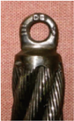 |
|||||
| Nominal Rope Diameter (mm) |
Crosby S-264 Pad Eye | Minimum Breaking Force (t) |
WLL Based on 3.15 Factor of Safety |
|||
| Size No. | Hole Dia. (mm) |
Overall Width (mm) |
||||
| 18-24 | 0 | 6.35 | 16 | 1.44 | 440 Kgs | |
| 25-30 | 1 | 9.65 | 22.4 | 2.0 | 630 Kgs | |
| 31-38 | 1.5 | 16.0 | 28.7 | 3.0 | 950 Kgs | |
| 39-52 | 2 | 19.1 | 38.1 | 6.0 | 1.9 t | |
| 53-64 | 4 | 25.4 | 54.0 | 8.0 | 2.5 t | |
| 65-84 | 5 | 31.8 | 67.0 | 12.8 | 4.0 t | |
| Type No.2 - Welded Modified Collared Eye Bolt | 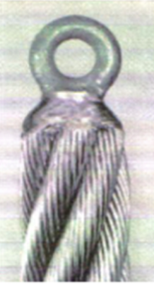 |
|||||
| Nominal Rope Diameter (mm) |
Crosby S-264 Pad Eye | Minimum Breaking Force (t) |
WLL Based on 3.15 Factor of Safety |
|||
| Size No. | Hole Dia. (mm) |
Overall Width (mm) |
||||
| 86-115 | M30 | 44 | 96 | 16 | 5.0 | |
| 117-125 | M36 | 54 | 118 | 25 | 7.9 | |
| >127 | M42 | 68 | 148 | 32 | 10.1 | |
Note: The welder shall be qualified by ‘representative weld test’, based upon the completion of welding and subsequent tensile testing of test assemblies. On successful completion of test, the operative shall be permitted to weld pulling eyes, on to ropes within the diameter range and construction as per those tested and the welders documented on their training records. Requalification is not required provided that a minimum of 3 welded pulling eyes are made during
any 12-month period.
Flexible type pulling Eye - Type no.4 (spliced)
This method of manufacture incorporates a hand-spliced loop formed in the IWRC of the rope, the outer strands hand tapered and laid around the core and the rope covered by wire serving and tape. Spliced pulling eyes are suitable for a range of rope sizes from 11 mm to 32 mm diameter, in rope grades up to 2160, produced using either galvanised or bright wires.
This method is only suitable for 6 and 8 stranded, single layer construction ropes with steel cores (not fibre cores) conforming to international standard, EN 12385-4, ISO 2408, ASTM A1023 and ISO 10425
The loop size shall be approximately 6 times the nominal rope diameter unless otherwise stated.
Notes:
1. It is not normally possible for the pulling eye formed by this method to be passed through a hole of the same nominal diameter as the main rope.
2. When using Dyform ropes the WLL of the pulling eye will be limited to the strength of the same diameter non-Dyform product.
3. Rope diameters larger than 32 mm are not normally terminated with Type No.4 pulling eyes. However, should the need arise then the WLL can be stated as equal to 1/5th of the calculated breaking load of the IWRC for the rope under consideration.
| Type No. 4 - Spliced Core | |||
| Nominal Rope Diameter (mm) |
Approximate IWRC Diameter (mm) |
Approximate IWRC Breaking Load (t) |
WLL of Becket Eye (t) |
| 11 | 4.4 | 1.25 | 0.25 |
| 12 | 4.8 | 1.5 | 0.3 |
| 13 | 5.2 | 1.5 | 0.3 |
| 14 | 5.6 | 2 | 0.4 |
| 16 | 6.5 | 2.5 | 0.5 |
| 18 | 7.3 | 3 | 0.6 |
| 19 | 7.6 | 3 | 0.6 |
| 20 | 8.1 | 4 | 0.8 |
| 22 | 8.8 | 5 | 1.0 |
| 24 | 9.6 | 6 | 1.2 |
| 25 | 10.0 | 6 | 1.2 |
| 28 | 11.3 | 7.5 | 1.5 |
| 30 | 12.1 | 9 | 1.8 |
| 32 | 12.9 | 10.5 | 2.1 |
Further guidance is available at contact@bridon-bekaert.com
Reference: TB.001 Ed.1April 2021 (EM-ME-WI-000161 - Type 1)